Inquiry
Form loading...



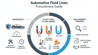
Choosing automotive fluid lines for global sourcing is a technical decision, not merely a purchasing exercise. These lines carry fuel, coolant, brake fluid, transmission oil, and refrigerant through demanding vehicle systems. A failed hose can cause leakage, overheating, fire risk, or an expensive recall. That is why material compatibility, pressure ratings, temperature limits, vibration resistance, and traceability deserve early attention.
Market conditions make the decision more complex. The International Energy Agency’s Global EV Outlook 2024 reported nearly 14 million electric car sales in 2023, representing about 18% of global car sales. This shift is changing demand for coolant, battery thermal-management, and refrigerant lines. At the same time, conventional vehicles still require large volumes of fuel, hydraulic, and oil-carrying assemblies. S&P Global Mobility has also highlighted continuing vehicle production complexity across regions and powertrains. Suppliers must therefore support different specifications without weakening quality control.
A practical sourcing review should compare rubber compounds, thermoplastics, reinforcement layers, fittings, test methods, and production capacity. It should also verify compliance with relevant requirements, such as IATF 16949 quality systems, ISO 14001 environmental management, and applicable SAE or OEM specifications. Ask for batch records. Inspect the crimp. Check the bend radius. Do not trust a polished sample alone.
The lowest quoted price may be misleading. Logistics, testing, tooling, and warranty exposure can change the total cost quickly. One overlooked detail can matter. A sound global sourcing strategy for automotive fluid lines combines engineering evidence, supplier audits, regional risk analysis, and honest review of uncertain assumptions. That approach is slower at the beginning, but often safer on the road.
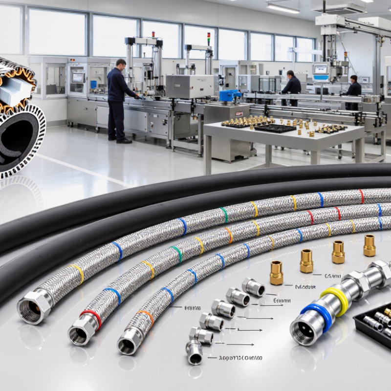
Before selecting automotive fluid lines for global sourcing, define the application precisely. Identify the fluid, temperature range, working pressure, pressure spikes, flow rate, and exposure time. Coolant, fuel, brake fluid, refrigerant, and hydraulic oil require different tube materials and barrier designs. SAE J30 and ISO 18752 provide useful performance frameworks, but they do not replace application testing.
Climate matters. A line used in northern winters may face severe flexibility loss, while an engine bay can exceed 150°C near heat sources. Salt spray, ozone, vibration, and repeated bending also change service life. The International Energy Agency’s Global EV Outlook 2024 reported nearly 14 million electric car sales in 2023. This growth increases demand for thermal-management lines around batteries, inverters, and charging systems. Their pressure behavior and electrical insulation needs may differ from traditional fuel systems. Do not assume one specification fits both.
Tips: Build a condition matrix before requesting quotations. Include minimum and maximum temperatures, burst pressure, impulse cycles, bend radius, media compatibility, and cleaning requirements. Ask suppliers for test evidence, not only catalog values. Verify samples after thermal aging and vibration testing. A perfect datasheet cannot predict every routing mistake. In practical sourcing reviews, small clamp movements often become large fatigue problems. I would also challenge overly broad service claims. They sound efficient, but they can hide missing data for local climates, assembly variation, or fluid chemistry.
| Application / Fluid | Typical Operating Temperature | Typical Pressure Range | Required Material Compatibility | Recommended Line Construction | Key Qualification Tests | Global Sourcing Checkpoints |
|---|---|---|---|---|---|---|
| Fuel supply and return Gasoline or diesel |
Approximately −40°C to 125°C, depending on routing and heat shielding | Typically 3–6 bar for low-pressure supply systems; high-pressure injection circuits require substantially higher ratings | Resistance to fuel permeation, ethanol-containing gasoline, diesel additives, ozone, heat, and vibration | Low-permeation elastomer tube with textile reinforcement; thermoplastic or multilayer construction may be used for reduced permeation | Pressure burst, impulse cycling, fuel immersion, permeation, ozone, heat aging, cold flexibility, and vibration testing | Confirm fuel chemistry, permeation limits, fitting retention, minimum bend radius, and regional fuel regulations before approving an equivalent material |
| Engine coolant Water-glycol coolant mixtures |
Approximately −40°C to 135°C; localized hot spots may be higher | Usually 1–2 bar in a pressurized cooling system, with transient pressure peaks possible | Compatibility with ethylene-glycol or propylene-glycol mixtures, corrosion inhibitors, deionized water, heat, and coolant additives | EPDM-based hose is commonly used; reinforced rubber or formed thermoplastic lines may be selected for shaped routes | Coolant immersion, heat aging, pressure cycling, burst, ozone, adhesion, clamp retention, and dimensional stability | Specify coolant formulation, concentration range, service-life target, clamp type, hose ID tolerance, and hot-environment routing requirements |
| Engine oil and turbocharger oil | Approximately −40°C to 150°C; turbocharger areas can require higher continuous temperature capability | Commonly 3–8 bar, with higher localized pressures depending on the circuit | Resistance to mineral and synthetic oils, detergents, oxidation products, high temperature, and external oil contamination | Oil-resistant elastomer tube with textile or wire reinforcement; heat-protective cover may be required near exhaust components | Hot-oil aging, pressure impulse, burst, flex fatigue, heat exposure, oil immersion, and fitting pull-off testing | Check maximum wall temperature rather than ambient temperature alone, especially near turbochargers, exhaust manifolds, and catalytic systems |
| Automatic transmission fluid | Approximately −40°C to 150°C, depending on cooler-line location | Typically 5–20 bar in cooler and lubrication circuits | Compatibility with synthetic transmission fluids, friction modifiers, seal materials, thermal aging, and contamination control requirements | Oil-resistant reinforced hose or formed thermoplastic tubing with suitable quick-connect or crimped fittings | ATF immersion, hot pressure cycling, burst, impulse, vibration, fitting retention, and permeation testing | Identify the exact fluid family, operating pressure, connection geometry, cleanliness level, and cooler-line temperature profile |
| Hydraulic brake fluid Glycol-ether or silicone-based systems |
Approximately −40°C to 150°C under normal service; fluid temperature can rise significantly during severe braking | Typically 70–150 bar in passenger-vehicle hydraulic circuits, with short-duration peaks possible | Must resist the specified brake-fluid chemistry, moisture exposure, pressure fatigue, abrasion, and temperature cycling | Low-expansion reinforced brake hose or rigid metal tubing with corrosion-resistant protective treatment | Volumetric expansion, burst, impulse, whip, adhesion, cold flexibility, heat aging, abrasion, and brake-fluid compatibility | Use only materials and fittings qualified for the designated brake-fluid class; dimensional expansion and pressure performance are safety-critical |
| Air-conditioning refrigerant Refrigerant and compressor oil mixture |
Approximately −40°C to 150°C; compressor discharge sections may experience higher temperatures | Roughly 8–35 bar depending on refrigerant, ambient temperature, and high- or low-side location | Low refrigerant permeation, compatibility with compressor oil, resistance to moisture, ozone, heat, and refrigerant pressure cycling | Barrier hose with elastomer inner tube, reinforcement layers, and protective outer cover; rigid sections may use aluminum or coated tubing | Refrigerant permeation, pressure burst, impulse, thermal cycling, vacuum resistance, ozone, vibration, and connector leakage | Confirm refrigerant type, pressure class, permeation requirement, fitting design, cleanliness, moisture control, and recovery-service compatibility |
| Diesel exhaust fluid / aqueous urea solution | Approximately −11°C to 80°C for the fluid circuit; freezing protection and thawing behavior must be considered | Typically below 10 bar in dosing and transfer circuits | Resistance to aqueous urea solution, crystallization, freeze-thaw cycles, hydrolysis products, and contamination | Dedicated compatible thermoplastic or elastomer tubing, often with heating capability in cold climates | Freeze-thaw cycling, chemical immersion, pressure cycling, crystallization, leakage, heater durability, and flow-rate verification | Control material cleanliness and avoid copper, zinc, and incompatible metals where they may contaminate the solution or dosing system |
| Power-steering hydraulic fluid | Approximately −40°C to 135°C, depending on proximity to the engine and exhaust system | Typically 70–150 bar in high-pressure circuits; return lines operate at much lower pressure | Compatibility with the specified hydraulic fluid, high-pressure pulsation, heat, ozone, abrasion, and vibration | High-pressure reinforced hose for supply lines; lower-pressure oil-resistant hose for return lines | Impulse, burst, pressure cycling, hot-oil aging, flex fatigue, abrasion, ozone, and fitting retention | Separate high-pressure and return-line specifications; verify pulsation frequency, routing, clamp loads, and noise-vibration requirements |
| Compressed air and pneumatic control Air suspension, actuation, or vehicle systems |
Approximately −40°C to 100°C, with higher localized temperatures near heat sources | Typically 6–12 bar in vehicle pneumatic systems | Resistance to compressed air, moisture, oil mist, ozone, abrasion, low temperature, and rapid pressure changes | Polyamide or reinforced thermoplastic tubing; flexible elastomer hose may be used at moving interfaces | Burst, pressure cycling, leakage, cold flexibility, abrasion, vibration, bend fatigue, and connector retention | Specify tube OD and wall tolerance, push-in fitting compatibility, routing protection, leakage limit, and installation tooling |
| Windshield washer fluid | Approximately −40°C to 80°C, depending on fluid formulation and under-hood exposure | Usually below 5 bar | Compatibility with water, alcohol-based solvents, detergents, dyes, preservatives, and low-temperature additives | Flexible low-pressure thermoplastic or elastomer tubing with suitable environmental resistance | Fluid immersion, freeze-thaw cycling, pressure leakage, aging, kink resistance, and connector retention | Confirm the lowest regional freezing point, fluid alcohol content, pump compatibility, connector type, and visible-line appearance requirements |